Parallax Mapping in an OpenGL Deferred Render Pipeline

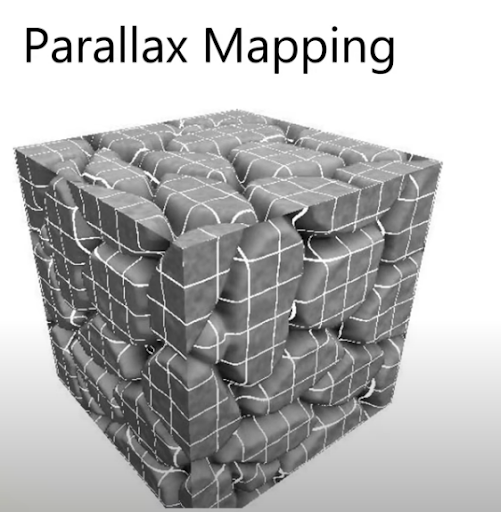
Parallax mapping is a technique for significantly increasing the detail of a surface without adding extra geometry. It is similar to displacement mapping, but instead of requiring additional geometry to create realistic depth, it offsets the surface texture coordinates based on the view direction and a height map. This project expands upon my deferred rendering pipeline to incorporate parallax mapping.
- TBN Matrix: In parallax mapping, texture coordinates are represented in tangent space, which is a local coordinate system where the normal, tangent, and bitangent vectors point in the positive up, right, and forward directions, respectively. To correctly calculate the parallax offset, the view direction vector must also be transformed into tangent space. This requires the use of a change of basis matrix, known as the TBN (Tangent, Bitangent, Normal) matrix.
-
Basis: A basis is a set of linearly independent vectors that span a vector space.
-
Change of Basis Matrix: A change of basis matrix is a matrix that is used to convert a vector from its representation in one basis to another.
For parallax mapping, the TBN matrix is constructed using the tangent, bitangent, and normal vectors at each vertex; however, 3D modeling software like Blender typically exports normal data, tangent and bitangent vectors are not included by default. If not explicitly included when exporting, these vectors must be computed either at runtime or during importing.
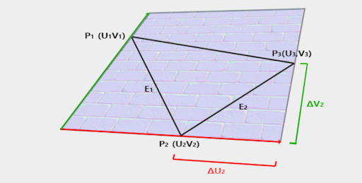
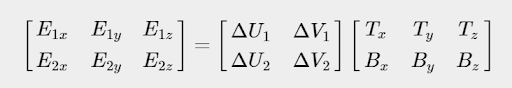
The tangent and bitangent vectors are derived from the texture coordinate and vertex position data. Specifically, the texture coordinate edges of a triangle can be expressed as a linear combination of the tangent and bitangent vectors. This relationship forms a system of linear equations that can be solved using the inverse of the texture coordinate differences.

For a right-handed coordinate system, the bitangent vector can alternatively be calculated using the cross product of the tangent and normal vector. Using the cross product method is generally more reliable because it is not dependent on the texture coordinate alignment with the surface geometry, which can sometimes be incorrect.
Once calculated, the tangent and bitangent vectors are transformed to world space, normalized to ensure an orthonormal basis, and stored in separate textures. Then in the parallax fragment shader, the TBN matrix is defined as the transpose of a matrix with column vectors tangent, bitangent, and normal.
Parallax mapping can introduce artifacts due to the orientation of texture coordinates across a mesh. Variations in the tangent and bitangent directions, influenced by texture coordinate orientation, often result in inconsistencies that make achieving correct results for all mesh faces challenging. This issue becomes especially difficult to handle with more complex meshes.
Blender provides an option to include tangent and bitangent data when exporting objects as .fbx files, which can simplify the process by eliminating the need to compute these vectors manually. I utilized this in a different version of the project than the one shown here. That method involves importing the mesh using Assimp, which removes the need for a custom vertex array. However, even with the mesh unwrapped using cube projection, a method that should generate accurate tangent and bitangent vectors, the same issue persisted.
Through experimentation, I found that flipping the bitangent vector during the creation of the TBN matrix significantly improved the parallax effect. While not a complete solution, this adjustment reduced visual artifacts and made the effect more reliable.
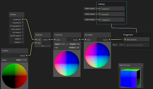
The view direction vector points from the current fragment position in the scene toward the camera position. It can be calculated by subtracting the fragment’s position in world space from the camera position. As mentioned previously, the TBN matrix is used to transform the view direction vector from world space to tangent space. The image below is taken from a Unity Universal Render Pipeline (URP) shader graph and provides a visual representation of that calculation. In this case, the transform node represents the view direction - TBN matrix multiplication.
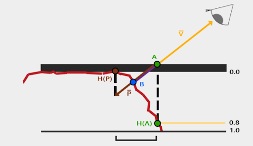
Parallax mapping can be implemented in several ways. The least computationally expensive method is to sample the displacement map at the point where the view direction vector intersects with the object. Using the displacement value at the intersection point, extend outward along the view direction vector by the same amount and sample the displacement map again at that location. This approximates the displacement effect and produces a convincing result when the view angle is not steep, but it breaks down as the view angle increases, causing the approximation to deviate significantly from the real displacement.
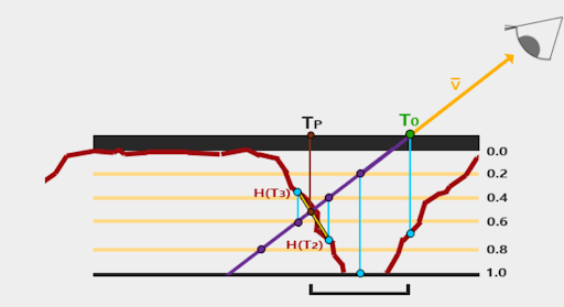
Steep parallax mapping is an alternative method that offers more accurate results. This method involves sampling the displacement map at multiple layers along the view vector until the sampled depth exceeds the displacement map’s value. To further refine the result, linear interpolation between the depth values before and after the intersection can be used. This approach is known as parallax occlusion mapping. In this project, I use steep parallax mapping.
Flowchart
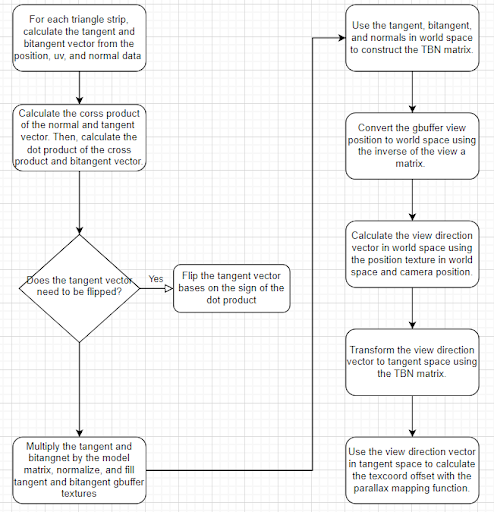
The following flowchart visualizes how the TBN matrix is computed in the G-buffer geometry pass and how it integrates with the parallax mapping process.
Implementation
This G-buffer geometry shader processes triangles by calculating tangent-space basis vectors (tangent, bitangent, and normal) required for parallax mapping and normal mapping. The fragment shader then stores the values in the corresponding output buffer.
    #version 330 core
    layout(triangles) in;
    layout(triangle_strip, max_vertices = 3) out;

    in vec3 gs_vertex_object_position[];
    in vec2 gs_vertex_object_texcoord[];

    in vec3 vsViewPos[];
    in vec3 vsModelPos[];
    in vec3 vsModelNormal[];
    in vec3 vsViewNormal[];

    out vec3 ModelNormal;
    out vec3 ViewNormal;
    out vec3 ViewPos;
    out vec3 ModelPos;
    out vec2 TexCoords;
    out vec3 Tangent;
    out vec3 Bitangent;

    uniform mat4 model;


    vec3 calculateSurfaceTangent(vec3 edge1, vec3 edge2, vec2 deltaUV1, vec2 deltaUV2) {
        vec3 tangent;
        float f = deltaUV1.x * deltaUV2.y - deltaUV2.x * deltaUV1.y;
        float epsilon = 0.0001;
        if (abs(f) < epsilon) {
            tangent = vec3(1.0, 1.0, 1.0); // fallback to a default value
        }
        else {
            f = 1.0 / f;
            tangent.x = f * (deltaUV2.y * edge1.x - deltaUV1.y * edge2.x);
            tangent.y = f * (deltaUV2.y * edge1.y - deltaUV1.y * edge2.y);
            tangent.z = f * (deltaUV2.y * edge1.z - deltaUV1.y * edge2.z);
            tangent = normalize(tangent);
        }
        return tangent;
    }

    vec3 calculateSurfaceBitangent(vec3 edge1, vec3 edge2, vec2 deltaUV1, vec2 deltaUV2) {
        vec3 bitangent;
        float f = deltaUV1.x * deltaUV2.y - deltaUV2.x * deltaUV1.y;
        float epsilon = 0.0001;
        if (abs(f) < epsilon) {
            bitangent = vec3(1.0, 1.0, 1.0); // fallback to a default value
        }
        else {
            f = 1.0 / f;
            bitangent.x = f * (-deltaUV2.x * edge1.x + deltaUV1.x * edge2.x);
            bitangent.y = f * (-deltaUV2.x * edge1.y + deltaUV1.x * edge2.y);
            bitangent.z = f * (-deltaUV2.x * edge1.z + deltaUV1.x * edge2.z);
            bitangent = normalize(bitangent);
        }
        return bitangent;
    }


    void main()
    {
        vec3 pos0 = gs_vertex_object_position[0];
        vec3 pos1 = gs_vertex_object_position[1];
        vec3 pos2 = gs_vertex_object_position[2];

        vec2 uv0 = gs_vertex_object_texcoord[0];
        vec2 uv1 = gs_vertex_object_texcoord[1];
        vec2 uv2 = gs_vertex_object_texcoord[2];

        vec3 edge1 = pos1 - pos0;
        vec3 edge2 = pos2 - pos0;

        vec2 deltaUV1 = uv1 - uv0;
        vec2 deltaUV2 = uv2 - uv0;


        // Calculate the normal, tangent, and bitangent vectors
        vec3 normal = normalize(vsModelNormal[0] + vsModelNormal[1] + vsModelNormal[2]);
        vec3 tangent = normalize(calculateSurfaceTangent(edge1, edge2, deltaUV1, deltaUV2));
        vec3 bitangent = normalize(calculateSurfaceBitangent(edge1, edge2, deltaUV1, deltaUV2));


        vec3 crossProduct = cross(normal,tangent);
        float dotProduct = dot(crossProduct, bitangent);

        // If the dot product is negative, invert the tangent vector
        if (dotProduct < 0.0)
        {
            tangent = -tangent;
        }

        for (int i = 0; i < 3; i++)
        {
            gl_Position = gl_in[i].gl_Position;
            ViewPos = vsViewPos[i];
            ModelPos = vsModelPos[i];
            TexCoords = gs_vertex_object_texcoord[i];
            ModelNormal = vsModelNormal[i];
            ViewNormal = vsViewNormal[i];
            Tangent = normalize(mat3(model) * tangent);
            Bitangent = normalize(mat3(model) * bitangent);
            EmitVertex();
        }

        EndPrimitive();
    }
When drawing the scene, this fragment shader reconstructs the TBN matrix from G-buffer textures, transforms positions and view vectors into tangent space, and applies parallax mapping to offset texture coordinates based on a displacement map. Using the output texture coordinates from parallax mapping, it samples the normal, albedo, and ambient occlusion data, then performs lighting calculations.
    #version 330 core

    out vec4 FragColor;

    in vec2 TexCoord;

    uniform sampler2D gViewPos;
    uniform sampler2D gNormal;
    uniform sampler2D gAlbedoSpec;
    uniform sampler2D gDisplacement;
    uniform sampler2D gTangent;
    uniform sampler2D gBitangent;
    uniform sampler2D gTexNormal;
    uniform sampler2D ssao;

    const float ParallaxSteps = 100.0; // number of steps for parallax mapping
    const float ParallaxHeightScale = 0.15; // height scale for parallax mapping

    struct PointLight
    {
        vec3  Position;
        float Intensity;
        vec3  Color;
        float Constant;
        float Linear;
        float Quadratic;
    };

    uniform PointLight lights[10];
    uniform int NR_LIGHTS = 3;
    uniform vec3 cameraPos;

    uniform mat4 invView;

    vec2 ParallaxMapping(vec2 texCoords, vec3 viewDir)
    {
        // number of depth layers
        const float minLayers = 30;
        const float maxLayers = 60;
        float numLayers = mix(maxLayers, minLayers, abs(dot(vec3(0.0, 0.0, 1.0), viewDir)));

        float numSteps = min(100, ParallaxSteps);
        // depth of current layer
        float currentLayerDepth = 0.0;
        // calculate the size of each layer
        float layerDepth = 1.0 / numSteps;

        // get initial values
        vec2  currentTexCoords     = texCoords;
        float currentDepthMapValue = texture(gDisplacement, currentTexCoords).r;

        // the amount to shift the texture coordinates per layer
        vec2 deltaTexCoords = viewDir.xy * ParallaxHeightScale / (viewDir.z * numSteps);


        for (float i = 0.0f; i < numSteps; i++)
        {
            if (currentLayerDepth < currentDepthMapValue)
            {
                // shift texture coordinates along direction of P
                currentTexCoords -= deltaTexCoords;
                // get depthmap value at current texture coordinates
                currentDepthMapValue = texture(gDisplacement, currentTexCoords).r;
                // get depth of next layer
                currentLayerDepth += layerDepth;
            }
            else
            {
                break;
            }
        }

        return currentTexCoords;

        // get texture coordinates before collision (reverse operations)
        vec2 prevTexCoords = currentTexCoords + deltaTexCoords;

        // get depth after and before collision for linear interpolation
        float afterDepth  = currentDepthMapValue - currentLayerDepth;
        float beforeDepth = texture(gDisplacement, prevTexCoords).r - currentLayerDepth + layerDepth;

        // interpolation of texture coordinates
        float weight = afterDepth / (afterDepth - beforeDepth);
        vec2 finalTexCoords = prevTexCoords * weight + currentTexCoords * (1.0 - weight);

        return finalTexCoords;
    }


    void main()
    {

        // Calculate TBN matrix
        vec3 T = vec3(texture(gTangent, TexCoord).xyz);
        vec3 B = vec3(texture(gBitangent, TexCoord).xyz);
        vec3 N = vec3(texture(gNormal, TexCoord).xyz);
        mat3 TBN = transpose(mat3(T, B, N));

        float D = dot(T,N);


        vec3 fragPos = texture(gViewPos, TexCoord).rgb;
        vec4 worldPos = invView * vec4(fragPos, 1.0);
        vec3 worldPos3 = worldPos.xyz / worldPos.w;

        vec3 objectView3 =  cameraPos - worldPos3 ;


        vec3 TangentFragPos = TBN * worldPos3;
        // Transform the camera position to tangent space
        vec3 TangentViewPos = TBN * cameraPos;

        // Calculate the view direction vector in tangent space
        vec3 viewDir = normalize(TBN * objectView3);


        // parallax mapping
        vec2 P = ParallaxMapping(TexCoord, viewDir);
        if(P.x > 1.0 || P.y > 1.0 || P.x < 0.0 || P.y < 0.0)
            discard;


        // obtain normal from normal map
        vec3 Normal = texture(gTexNormal, P).rgb;
        Normal = normalize(Normal * 2.0 - 1.0);
        // get diffuse color
        vec3 Diffuse = texture(gAlbedoSpec, P).rgb;
        // get ambient occlusion
        float AmbientOcclusion = texture(ssao, P).r;


        // apply lighting
        vec3 Lighting = vec3(0.0);
        for (int i = 0; i < NR_LIGHTS; ++i)
        {
            vec3 TangentLightPos = TBN * lights[i].Position;
            vec3 lightDir = normalize(TangentLightPos - TangentFragPos);

            // diffuse
            vec3 diffuse = max(dot(Normal, lightDir), 0.0) * Diffuse * lights[i].Color * lights[i].Intensity;

            // specular
            vec3 reflectDir = reflect(-lightDir, Normal);
            vec3 halfwayDir = normalize( lightDir+ viewDir );
            float spec = pow(max(dot(reflectDir, halfwayDir), 0.0), 64); // adjusted exponent
            vec3 specular = lights[i].Color * spec * lights[i].Intensity;

            // attenuation
            float distance = length(TangentLightPos - TangentFragPos);
            float attenuation = 1.0 / (lights[i].Constant + lights[i].Linear * distance + lights[i].Quadratic * distance * distance);
            diffuse *= attenuation;
            specular *= attenuation;

            Lighting += diffuse + specular;
        }

        // apply ambient occlusion to the new lighting
        vec3 Ambient = vec3(0.5 * Diffuse); //* AmbientOcclusion;
        Lighting += Ambient;

        // output the final color
        FragColor = vec4(Lighting, 1.0);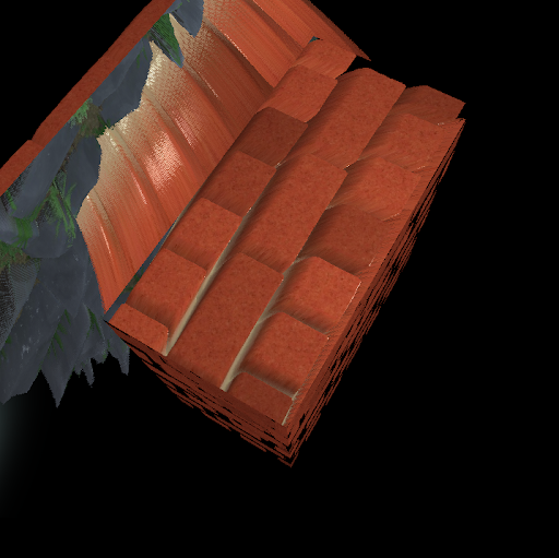
}When two parallax-mapped objects intersect, stretching artifacts can occur due to the algorithm assuming a continuous surface. These artifacts arise because the parallax mapping technique displaces texture coordinates without accounting for depth discontinuities between objects that intersect. A more advanced technique, such as parallax occlusion mapping with depth-aware adjustments, can help solve this issue.
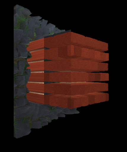
Additionally, if the tangent and bitangent vectors are misaligned, the parallax effect may shift incorrectly relative to the view direction, causing unrealistic movement, as demonstrated on the top quad of the cube.