Physically-Based Sky & Cloud Rendering
- Overview
- Cloud Color Buffer Structure
- TAAU Pass
- Light Shaft Pass
- High Altitude Clouds Pass
- Composite Pass
- Weather System
- Future Work
- Resources
Compositing is one of the more technically demanding parts of a real-time rendering pipeline when working with volumetrics, transparents, and atmospheric effects. In volumetric rendering, holdouts are commonly used to mask out regions of the volume that shouldn’t contribute to the final image (such as areas occluded by foreground geometry). This ensures that volumetric effects like clouds respect object silhouettes and depth.
In offline rendering, deep shadow maps are often used to represent semi-transparent holdouts, as they provide a convenient way to store the transmittance function needed for accurate compositing. However, generating and sampling these maps is computationally expensive, and in my case, I found them too costly for real-time use. As an alternative, geometric holdouts can be treated as fully opaque, and the necessary occlusion information can be passed from the volumetric pass to compositing using just the scene depth buffer. In this approach, transparents are just drawn after compositing with the scene.
One-sided holdouts are commonly used for volumetrics, where surfaces are rendered in full and only the volumetric pass masks out geometry. While this approach is not technically accurate, it can produce acceptable results for real-time rendering. However, it often introduces matte lines (artifacts caused by incorrect blending at the edges of objects), which become especially noticeable when using a downsampled volumetric pass. I found that resolving this problem, or at least reducing how noticeable it is, requires that the geometric occlusion information be upsampled and anti-aliased before being used when compositing, which requires carefully planning out the pipeline.
For performance reasons, atmosphere scattering and transmittance are often precomputed and stored in multiple LUTs. This adds an extra dimensionality to compositing, as multiple texture lookups are required to have the geometry and volumetric image be consistent with the surrounding atmosphere, such as with rendering the aerial perspective effects mentioned in A Scalable and Production Ready Sky and Atmosphere Rendering Technique 1.
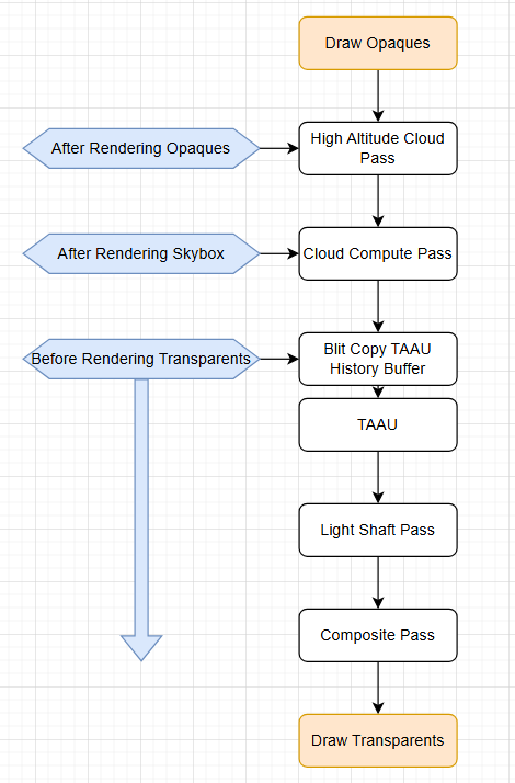
Ultimately, I designed a multi-part compositing approach that utilizes a slightly modified version of Scrawk’s Unity port of Eric Bruneton’s precomputed atmospheric scattering 2,3. This approach includes geometric holdout masking through depth information that is upsampled using TAAU and calculating and modifying per-pixel atmospheric scattering to maintain visual consistency across different lighting conditions, including transitions from day to night. The following flowchart outlines the structure of my pipeline:
This post continues from my previous write-up on real-time volumetric rendering optimizations. Here, I’ll cover new additions to the project, including:
- improving visual quality
- implementing further real-time optimizations
- compositing volumetrics with scene geometry for use in a game environment
My end goal for this project is to use it as a skybox in a stylized, retro-style game. To achieve that aesthetic, I use the common approach that uses color quantization combined with a downsampling and upsampling passes.
The cloud color buffer is structured in the following way:
- R Channel: scattering
- G Channel: ambient contribution
- B Channel: estimated cloud depth
- A Channel: transmittance
The Ideal Solution and Constraints:
Ideally, we would like to use a float3 to represent scattering and transmittance so that we can achieve a more accurate and flexible simulation of wavelength-dependent effects by specifying a scattering coefficient and extinction coefficient. However, we need to output both the scattering and transmittance in the output buffer, since both are later required for compositing. This means we already have to sacrifice some information to represent scattering and transmittance this way. We could solve the problem using two output buffers, but then we would have to run both through TAAU, which isn’t really feasible for performance reasons.
The composite pass requires upsampled depth information to accurately composite the precomputed atmosphere with the TAAU output, since we need the depth information for compositing with multiple radiance sources and for using world position to sample our atmosphere lookups. Without upsampled depth information, we get artifacts on edge pixels due to the downsampled depth buffer.
Trying to upsample the depth buffer separately from the cloud pass’s color output would be too expensive to be a feasible option (again, we can only really afford to run TAAU once), so instead the depth information has to be encoded into the cloud pass color output and upsampled at the same time as the scattering and transmittance.
Solution:
Initially, I tried to keep scattering as a float3 and sacrifice transmittance information by representing it as a float. In order to include depth in the buffer, I used Principal Component Analysis to define a color space for the scattering that could be represented by a float2, which is possible because the base scattering of clouds—excluding atmospheric contribution—does not vary significantly.
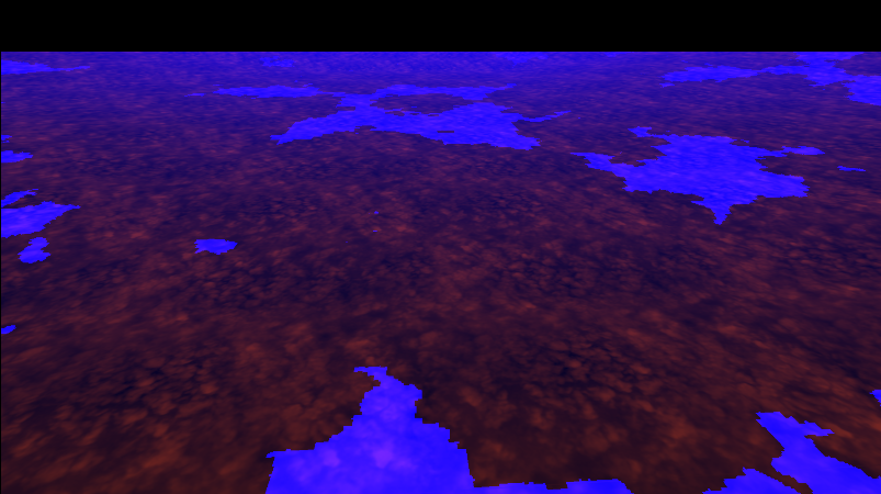
However, I ended up switching to using just a float representation for both scattering and transmittance, thereby sacrificing the ideal solution, because it gives more control in the composite pass for modifying the final scattering color. Since we now have an unused channel, I output a value to control the ambient color influence, which I moved from being applied in the raymarching loop to the composite pass. Below is the output of the composite pass, followed by a breakdown of each individual channel:
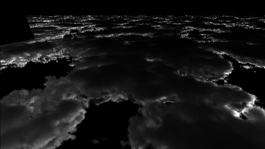
Scattering (R)
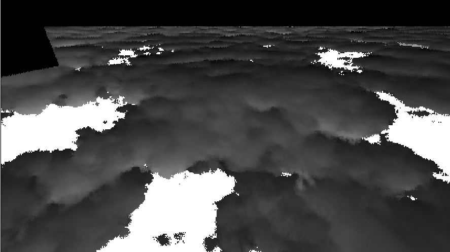
Ambient Contribution (G)
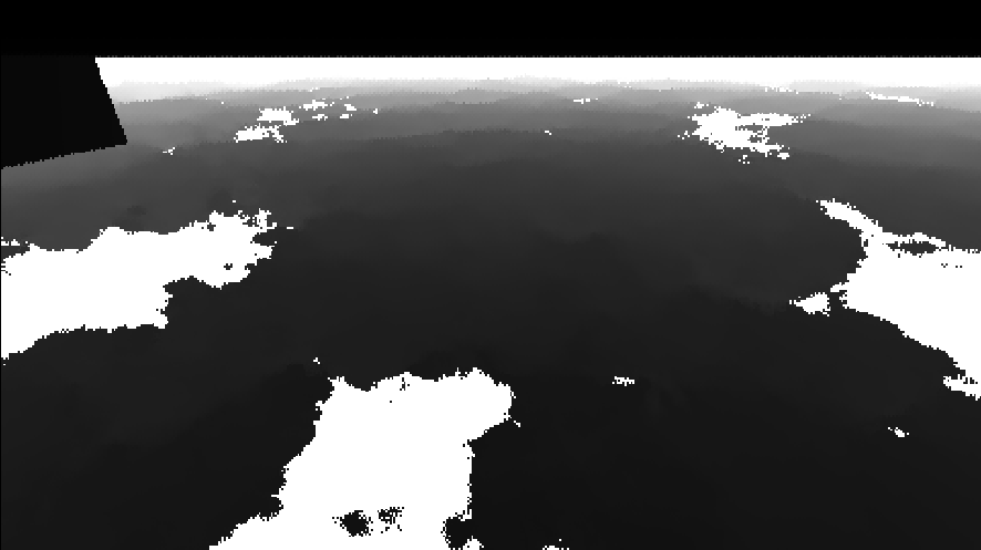
Depth (B)
Transmittance (A)
High-altitude clouds are implemented using the same approach described in the presentation Nubis: Authoring Real-Time Volumetric Cloudscapes with the Decima Engine 4. In this method, a high-resolution texture is applied to a mesh and rendered to a full-resolution target.
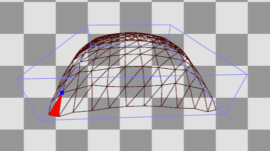
To composite high-altitude clouds with the rest of the scene, the high altitude color buffer is structured the same as the compute buffer. Scattering, layer height,depth, and transmittance are computed in the following ways:
- cloud scattering is represented by the high resolution texture
- cloud height is just a constant value
- depth is the depth to the mesh if the transmittance is greater than 0
- transmittance is evaluated using a coverage map
The TAAU Pass is a modified version of this temporal wavlet upscaling implementation, where the current color is computed using weighted neighborhood sampling blended with a history sample. My version introduces several additions which are required to handle a dynamic scene: I modified that implementing to use a dynamic sharpness value based on scene motion, use depth aware filtering to better handle edges, use motion vectors for reprojection, constrain the history, and use a luminance-based feedback weight as utilized in the Temporal Reprojection Anti-Aliasing in INSIDE 5.
float4 TemporalUpSample(float2 uv, float ss_vel_mag)
{
float2 I2 = RENDERSCALE * (uv * OUTPUT_TEXEL_SIZE.zw );
// k should depend on the amount of motion in the scene.
// Defines the sharpness of the filtering (used for Gaussian-like smoothing)
float k = lerp(80,1.2, saturate(ss_vel_mag * 20));
// Size of the filter kernel. A kernel size of 1 means a 3x3 neighborhood
// (one pixel around the center pixel). This can be increased for more smoothing.
int kernell = 1;
float4 cmin = 1.0, cmax = 0.0;
float s = 0.0;
float4 O = 0.0;
float4 centerSample = SampleCurrentFrame(uv);
float centerDepth = centerSample.b;
// Some far value that will just never be greater than the sampled depth
float closest_depth = 1000000.0;
float2 closest_frag = uv;
for (int x = -1; x <= 1; x++)
{
for (int y = -1; y <= 1; y++)
{
// Loop through neighboring texels
float2 c = float2((float)x, (float)y);
float2 offset = CalculateJitterOffset(I2, c);
float2 uvCurrSample = (I2 + c) / INPUT_TEXEL_SIZE.zw;
float4 t = SampleCurrentFrame(uvCurrSample);
//larger kernell if no temporal data to avoid dark spots
float w = exp2(-(_iFrame==0?.25/RENDERSCALE:k)*dot2(offset-frac(I2)));
#if USE_DILATION
UpdateClosestFrag(t.b, uvCurrSample, closest_depth, closest_frag);
#endif
//Depth-aware filtering
w *= abs(centerDepth - t.b) > EDGE_REJECT_THRESHOLD ? _EdgeRejectWeight : 1.0;
// Color min and max
cmin = min(cmin, t);
cmax = max(cmax, t);
O += t * w;
s += w;
}
}
float4 currentFrame = O / s;
float history_s = min(acos(-1.) / k * float(_iFrame), 2.0);
#if USE_MOTION_HISTORY_SAMPLE
#if USE_DILATION
float2 ss_vel = SampleMotion(closest_frag);
#else
float2 ss_vel = SampleMotion(uv);
#endif
float4 reproj = SamplePreviousFrame(uv - ss_vel);
#else
float4 reproj = SamplePreviousFrame(uv);
#endif
// clamp history to neighbourhood of current sample
#if USE_CLIPPING
float4 constrainedHistory = clip_aabb(cmin.xyz,
cmax.xyz,
clamp(currentFrame, cmin, cmax),
reproj);
#else
float4 constrainedHistory = clamp(reproj, cmin, cmax);
#endif
float4 weightedPreviousFrameSample = constrainedHistory * history_s;
O += weightedPreviousFrameSample;
s += history_s;
float4 filteredResult = O / s;
#if USE_LUMINANCE_FEEDBACK
// --- Lottes-style luminance-based feedback weight ---
#if USE_YCOCG
float lumFiltered = filteredResult.r;
float lumCurrent = currentFrame.r;
#else
float lumFiltered = Luminance(filteredResult.rgb);
float lumCurrent = Luminance(currentFrame.rgb);
#endif
float unbiasedDiff = abs(lumFiltered - lumCurrent) / max(lumFiltered, max(lumCurrent, 0.2));
float unbiasedWeight = 1.0 - unbiasedDiff;
float unbiasedWeightSqr = unbiasedWeight * unbiasedWeight;
float k_feedback = lerp(_FeedbackMin, _FeedbackMax, unbiasedWeightSqr);
// --- Final blend: between filtered temporal result and current frame ---
return lerp(currentFrame, filteredResult, k_feedback);
#else
return filteredResult;
#endif
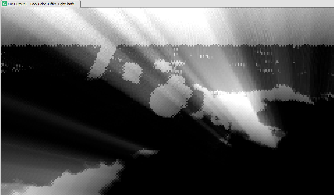
}Light shafts, also known as crepuscular rays, are a key visual feature that enhance atmospheric depth and realism. While they can be rendered by ray marching through a constant participating medium, this method is too expensive to be practical for real-time rendering.
Instead, I implemented light shafts as a post-processing pass, following the screen-space technique described by Kenny Mitchell 6 that is also described in the Guerilla Games presentation Nubis: Authoring Real-Time Volumetric Cloudscapes with the Decima Engine 4. This approach simulates volumetric scattering by performing a radial blur from each pixel toward a projected light source. Along each ray, the brightness is sampled from the scene texture, with each sample decaying exponentially to mimic light attenuation. The result is modulated by weight and exposure, and this creates a good enough approximation of volumetric light scattering at a much lower cost as the prior method mentioned. We do still have to perform an expensive loop in this pass, but since it can be rendered at a lower resolution and bilinearly sampled without too much of a tradeoff in quality, the performance is acceptable.
float4 Scattering (float2 texCoord,
                    float2 ScreenLightPos,
                    float density,
                    float weight,
                    float decay,
                    float exposure)
{
    // Calculate vector from pixel to light source in screen space.
    half2 deltaTexCoord = (texCoord - ScreenLightPos.xy);
    // Divide by number of samples and scale by control factor.
    deltaTexCoord *= 1.0 / NUM_SAMPLES * density;


    // Add jitter to starting texCoord based on IGN
    float noise = IGN(texCoord * _ScreenParams.xy); // Screen-space noise
    float jitterOffset = noise;
    texCoord -= deltaTexCoord * jitterOffset;


    // Store initial sample.
    half3 color = SampleMainTexture(texCoord);
    // Set up illumination decay factor.
    half illuminationDecay = 1.0;
    // Evaluate summation from Equation 3 NUM_SAMPLES iterations.
    for (int i = 0; i < NUM_SAMPLES; i++)
    {
        // Step sample location along ray.
        texCoord -= deltaTexCoord;
        // Retrieve sample at new location.
        half3 sample = SampleMainTexture(texCoord);
        // Apply sample attenuation scale/decay factors.
        sample *= illuminationDecay * weight;
        // Accumulate combined color.
        color += sample;
        // Update exponential decay factor.
        illuminationDecay *= decay;
    }

    // Output final color with a further scale control factor.
    return float4(color * exposure, 1);
}
Currently, my implementation uses a slightly modified version of a Unity implementation of Brunetons improved atmospheric scattering which precomputes single scattering, multiple scattering, and transmittance. Opting to perform multiple textures samples to calculate radiance rather than performing additional raymarching through the atmosphere that would otherwise be required.
We have 3 layers that we have to blend together: the background atmosphere, the scene, and the clouds.
-
Atmosphere:
The atmospheric scattering and transmittance are just a texture lookup. - Scene:
To calculate the scene radiance:- We incorporate the sun irradiance and sky irradiance into the scene color.
- Then, we modulate it by the aerial perspective transmittance, which indicates how much of the scene color reaches the camera without being scattered or absorbed by the atmosphere.
- (We multiply it by
(1 / SCENE_EXPOSURE)first to counteract the exposure operator applied later.) - Finally, we add the inscattering from the atmosphere between the scene position and the camera.
- Clouds:
We follow a similar process with cloud radiance, with some key differences:- Ideally, we’d compute the same sun and sky irradiance for the cloud scattering color, but volumetric clouds don’t have well-defined surface normals. Instead, since cloud lighting is governed by accumulated in-scattering (which inherently includes light direction, view angle, and phase function), we can substitute the diffuse lighting factor
max(dot(normal, sun_direction), 0.0)with the cloud scattering color for solar irradiance. This substitution isn’t perfect, as it doesn’t reproduce the distinct highlights typically visible on the sun-facing portions of clouds.
- Ideally, we’d compute the same sun and sky irradiance for the cloud scattering color, but volumetric clouds don’t have well-defined surface normals. Instead, since cloud lighting is governed by accumulated in-scattering (which inherently includes light direction, view angle, and phase function), we can substitute the diffuse lighting factor

- This substitution does not work for sky irradiance. So instead, the cloud world position is used to approximate the surface normal.
- The rest of the radiance calculation is essentially the same as the scene radiance. We scale the cloudScattering by the aerial perspective transmittance, etc.
- In addition to aerial perspective scattering, we add the Mie scattering from the atmosphere, modulated by the light shaft mask, to ensure that the mie scattering also affects the cloud color. This helps achieve more accurate colors during sunrise / sunset.
These layers are then composited back to front.
- Atmosphere: If the view ray intersects scene geometry, the atmospheric radiance is excluded (i.e., set to zero). Otherwise, we accumulate contributions from Rayleigh and Mie scattering as well as light from stars.
- Sun and Moon: If the view ray intersects the sun or moon, their radiance is added—scaled by the atmospheric and cloud transmittance along the ray.
- Scene and Clouds: To correctly composite scene geometry with clouds, we compare the scene and cloud depths. If the scene appears in front of the clouds, we blend in the scene radiance before adding the cloud radiance; otherwise, the order is reversed.
// For calculating the final radiance, we start with the atmosphere radiance.
// If there is an object in the scene, then we set the atmosphere contribution to 0.
// We do this because we handle the scene radiance as its own thing.
float3 finalRadiance = sceneDepth > 0.000001 ? 0 : starContribution * atmoTransmittance +
                                                    rayleighScattering +
                                                    mieScattering * MIE_STRENGTH;


// If the view ray intersects the Sun, add the Sun radiance
if (dot(view_direction, sun_direction) > sun_size.y)
{
    finalRadiance += atmoTransmittance *
                        (intersectsScene ? 0.0 : 1.0) *
                        (1-combinedCloudTransmittance) *
                        GetSolarRadiance();
}


// If the view ray intersects the Moon, add the Moon radiance
if (dot(view_direction, -sun_direction) > moon_size.y)
{
    finalRadiance += atmoTransmittance * // atmosphere Transmittance
                        (intersectsScene ? 0.0 : 1.0) * // scene Transmittance
                        (1-combinedCloudTransmittance) * // cloud Transmittance
                        GetSolarRadiance();
}
if(drawCloudsOverScene)
{
    // Here we add the scene radiance, and then the cloud radiance.
    finalRadiance = lerp(finalRadiance, sceneRadiance, intersectsScene ? 1 : 0);
    finalRadiance = lerp(finalRadiance, cloudRadiance, combinedCloudTransmittance);
}
else
{
    // Here we add the cloud radiance, and then the scene radiance.
    finalRadiance = lerp(finalRadiance, cloudRadiance, combinedCloudTransmittance);
    finalRadiance = lerp(finalRadiance, sceneRadiance, intersectsScene ? 1 : 0);
}
And then scene radiance and cloud radiance are calculated in the following manner:
// Scene Radiance:
#if USE_AERIAL_PERSPECTIVE_SCENE

    float3 sceneRadiance = 0.0, sceneAerialTransmittance = 0.0;

    // If there is an object in the scene, compute the transmittance and
    // inscattering of the atmosphere to that position. If there is not
    // an object in the scene, then we don't have to do anything.

    if(intersectsScene)
    {
        // Scale by our atmosphere scale
        worldPos *= ATMOSPHERE_SCALE;

        float3 sky_irradiance;
        float3 sun_irradiance = GetSunAndSkyIrradiance(worldPos - earth_center,
                                                        sceneNormal,
                                                        sun_direction,
                                                        sky_irradiance);

        // Keep the sky irradiance above a minimum value
        sky_irradiance = max(sky_irradiance, SCENE_MIN_IRRADIANCE);

        float sunVis = 1.0;
        float skyVis = 1.0;

        // Get Sky Radiance To Point and Transmittance between the camera and the scene world position
        float3 sceneAerialInScatter = GetSkyRadianceToPoint(camera - earth_center,
                                                                worldPos - earth_center,
                                                                0,
                                                                sun_direction,
                                                                true,
                                                                sceneAerialTransmittance);

        // prevent undefined in scattering
        sceneAerialInScatter = max(sceneAerialInScatter, 0.0);

        // To calculate the scene radiance, we modulate the scene color by the
        // aerial perspective transmittance, which says how much of the scene color makes it
        // to the camera without being reflected or absorbed by the atmosphere.
        // ( We multiply it by "( 1 / SCENE_EXPOSURE)" first because we apply
        // exposure before returning the final radiance. We don't really want
        // to be applying this exposure operator to the scene, so we counteract
        // what is done in the final step here. ) And then we just add the inscattering
        // from by the atmosphere from the scene position to the camera, which is
        // how much light is added by the atmosphere.

        // Lambertian factor
        float3 lighting = max((sun_irradiance * sunVis + sky_irradiance * skyVis), eps) *
                          (1.0 / PI);

        sceneRadiance = lighting * sceneColor.rgb * (1 / SCENE_EXPOSURE) *
                        sceneAerialTransmittance +
                        sceneAerialInScatter;
    }

#else
    // If we are not using the aerial perspective radiance for the scene,
    // then we just use the scene color.
    float3 sceneSkyViewTransmittance = 0.0;
    float3 sceneRadiance = sceneColor.rgb * (1 / exposure);
#endif


// Clouds Radiance:

// Add rayleigh scattering to clouds modulated by the distance to blend
// to atmosphere color over distance. This is a cheaper way to at least
// have some fade out over distance for clouds on the horizon.
float3 cloudRayleighScattering = rayleighScattering * combinedLinearCloudDepth;

// We just combine the cloud scattering with the rayleight distance fade
// out, and then add mie scattering modulated by the light shaft mask.
// Again, this helps to get the correct colors during sunrise / sunset.

float3 cheapCloudRadiance = combinedCloudScattering +
                            cloudRayleighScattering +
                            mieScattering * MIE_STRENGTH * lightShaftMask;

#if USE_AERIAL_PERSPECTIVE_CLOUD

    // If using the aerial perspective radiance for clouds, we need to compute the
    // transmittance and radiance to the cloud position
    float3 cloudWorldPos = camera +
                           view_direction *
                           Linear01ToEyeDepth(combinedLinearCloudDepth, nearPlane, farPlane);

    // Scale by our atmosphere scale
    cloudWorldPos *= ATMOSPHERE_SCALE;

    float3 cloud_sky_irradiance;
    float3 cloud_sun_irradiance = GetSunAndSkyIrradianceCloud((cloudWorldPos - earth_center) -
                                                              float3(0, 2000, 0) * ATMOSPHERE_SCALE,
                                                              -normalize(earth_center - cloudWorldPos),
                                                              length(combinedCloudScattering),
                                                              sun_direction,
                                                              cloud_sky_irradiance);

    // Account for global illumination from stars
    cloud_sky_irradiance = lerp(cloud_sky_irradiance, 1.0, STARS_GLOBAL_ILLUMINATION);

    // Get Sky Radiance To Point and Transmittance between the camera and the cloud world position
    float3 cloudAerialTransmittance;
    float3 cloudAerialInScatter = GetSkyRadianceToPoint(camera - earth_center,
                                                        cloudWorldPos - earth_center,
                                                        0,
                                                        sun_direction,
                                                        false,
                                                        cloudAerialTransmittance);

    // prevent undefined inscattering
    cloudAerialInScatter = max(cloudAerialInScatter, 0.0);

    float sunVis = 1.0;
    float skyVis = 1.0;

    // We scale the cloudScattering by just a variable to control the weight,
    // and then by the aerial transmittance.  This represents how much of the
    // cloud scattering makes it from the cloud through the atmosphere to the camera.
    // We then add the light (from the atmosphere) that is in scattered along the
    // path from the clouds to the camera. And then we add the Mie scattering from
    // the atmosphere, modulated by the light shaft mask, to ensure that the
    // mie scattering also effects the cloud color. This helps to get the
    // correct colors during sunrise / sunset.

    // Lambertian factor
    float3 lighting = max(cloud_sun_irradiance * sunVis + cloud_sky_irradiance * skyVis, eps) *
                      (1.0 / PI);

    float3 cloudRadiance = lighting * combinedCloudScattering *
                            cloudAerialTransmittance +
                            cloudAerialInScatter +
                            mieScattering * MIE_STRENGTH * lightShaftMask;


    cloudRadiance = lerp(cheapCloudRadiance,
                         cloudRadiance,
                         lerp(CLOUDS_AERIAL_WEIGHT,
                              CLOUDS_AERIAL_NIGHT_WEIGHT,
                              saturate(nightFactor * 60)));
#else
    float3 cloudRadiance = cheapCloudRadiance;
#endif
A weather system drives cloud animation by blending between different weather states. Each weather state consists of:
- Scheduling parameters that define when the state can occur and how likely it is to be selected during specific times of day.
- Cloud and weather settings that determine cloud coverage, appearance, and overall atmospheric conditions.
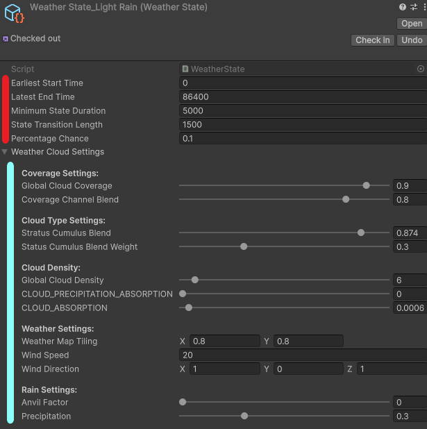
The weather system uses a user-defined interval to periodically check whether to transition to a new weather state. Rather than using a structured finite state machine, I simply iterate through all defined weather states in a loop. Then when a new state is selected, I blend between the previous state and the new state over state’s transition length using a simple lerp between the previous and new state’s properties and passing that to the compute shader.
void UpdateAutomaticMode()
{
    // Check if it's time to transition to the next weather state
    if (timeSinceLastUpdate >= weatherUpdateInterval)
    {
        RollForWeatherStateTransition();
        timeSinceLastUpdate = 0f;
    }

    // Perform blending every frame while in transition
    if (weatherStateDuration < currentWeatherState.stateTransitionLength)
    {
        blendFactor = Mathf.Clamp01(weatherStateDuration / currentWeatherState.stateTransitionLength);
        BlendToCurrentWeatherState();
    }
}

void RollForWeatherStateTransition()
{
    bool canTransition = weatherStateDuration >= currentWeatherState.minimumStateDuration;
    if(!canTransition) return;

    // roll for the next weather state, certain states can only occur at certain times during the day,
    foreach (WeatherState weatherState in weatherStates)
    {
        // Check if the current time is within the range for this weather state
        if (timeOfDaySeconds >= weatherState.earliestStartTime &&
            timeOfDaySeconds <= weatherState.latestEndTime &&
            currentWeatherState != weatherState) // Ensure we are not transitioning to the same state
        {
            // roll for the transition to that weather state
            float randomValue = Random.Range(0f, 1f);
            if (randomValue < weatherState.percentageChance)
            {
                // Transition to this weather state
                TransitionToWeatherState(weatherState);
                break; // Exit the loop after transitioning
            }
        }
    }
}Remaining Technical Challenges:
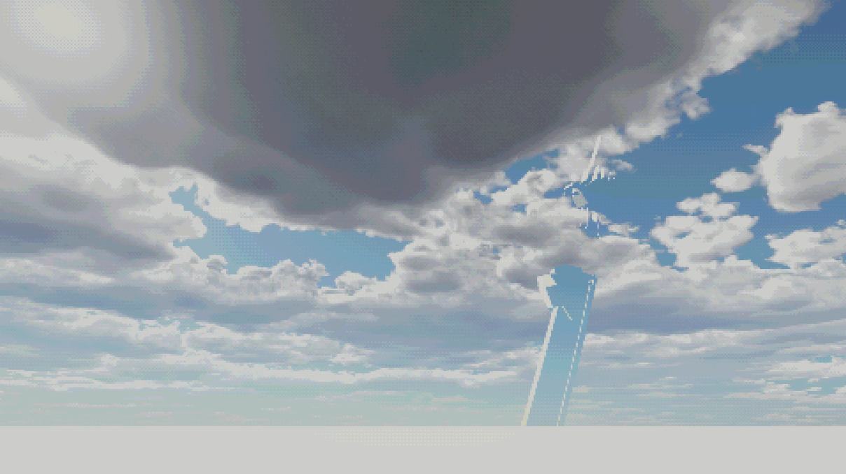
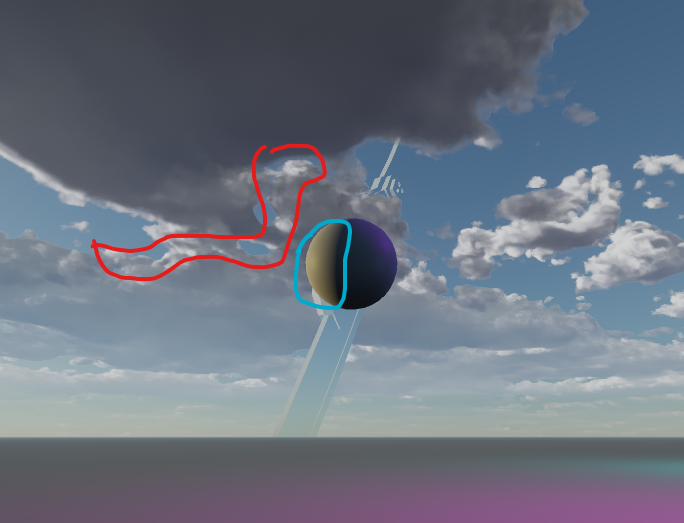
There are still a couple of problems that need to be solved to realistically use this render feature in a game.
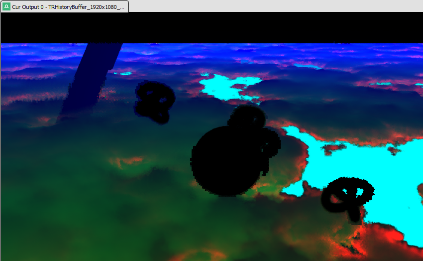
To avoid overdraw in the cloud pass, I sample the scene depth buffer, setting the maximum distance of the raymarch to the scene intersection. In my cloud pass, I output this depth combined with the cloud depth in the blue channel so that it can be upsampled through TAAU. When compositing, I then use this depth information to determine compositing order, which should work fine in theory as long as it is upsampled correctly through TAAU. However, with my current implementation, when objects in the scene are in motion, the history sample isn’t reprojected correctly, resulting in artifacts where parts of moving objects appear pixelated in the output, as shown in the image below. I’ve tried several approaches to resolve this issue. I believe it is due to using a low-resolution motion vector buffer; the buffer size matches the downsampled cloud buffer, and the artifact becomes more pronounced at lower render scales. I can’t solve the issue simply by upsampling the motion vector buffer or switching to the full-resolution scene motion vector buffer for scene objects, so I presume the solution involves using a more complex history restraining method, reducing overdraw in the cloud pass, or performing some other post-processing of the motion vector buffer.
With my end goal being to use the skybox in a retro-style game, I’m sure there are additional optimizations specific to that pipeline that I’d like to explore in the future. However, given how my pipeline is set up, I expect technical challenges I will need to solve, since I can’t easily reduce the size or precision of my TAAU buffer without sacrificing the depth information required for compositing.
Lighting Model Improvements
I also want to improve the cloud quality, the main issue is with how I am calculating the beer powder factor. To get the beer powder term to show up in the final image I had to scale the low lod density sample by a large amount and introduce a phase weight term to control the phase probability influence, both of which were not included in the Nubis example implementation in the presentation Nubis: Authoring Real-Time Volumetric Cloudscapes with the Decima Engine 4. And even then, getting an output that has the beer powder term push through the phase function without washing it out is very finicky requiring adjusting properties like density that hurt the overall appearance.
I also want to improve the cloud quality. The main issue is with how I am calculating the “beer powder” factor. To get the “beer powder” term to show up in the final image, I had to scale the low LOD density sample by a large amount and introduce a phase weight term to control the phase probability influence. Both of these were not included in the Nubis example implementation in the presentation Nubis: Authoring Real-Time Volumetric Cloudscapes with the Decima Engine 4. And even then, producing an output where the “beer powder” term pushes through the phase function without washing out is very finicky and requires adjusting properties like density, which hurts the overall appearance.
Below is the HLSL function I use to calculate the light energy, incorporating the “beer powder” approximation through representing the surrounding media with a low LOD density sample.
float GetLightEnergy(float heightPercentage,
                      float sigmaE,
                      float dsLoded,
                      DirectionalLight DIR_LIGHT,
                      float phase_probability,
                      float mu,
                      float dd)
{
    dsLoded *= BEER_POWDER_AMOUNT;

    // **Attenuation Approximation**
    float primary_attenuation = exp(-sigmaE * dd);
    float secondary_attenuation = exp(-sigmaE * dd * 0.25) * 0.7;
    float attenuation_probability = max( remap(mu, 0.7, 1.0, secondary_attenuation, secondary_attenuation * 0.25), primary_attenuation);

    // **Beer Powder Approximation with In-Scattering Probability**
    float depth_probability = lerp( 0.05 + pow(max(dsLoded,0), SafeRemap(heightPercentage, 0.3, 0.85, 0.5, 2.0)),
                                    1.0,
                                    saturate(sigmaE / dd));

    float vertical_probability = pow(SafeRemap(heightPercentage, 0.07, 0.14, 0.1, 1.0), 0.8);
    float in_scatter_probability = depth_probability * vertical_probability;


    float phase_weight = lerp(phase_probability, 1.0, saturate(dsLoded * 0.5));
    return attenuation_probability * in_scatter_probability * phase_weight * DIR_LIGHT.intensity.x;
}
Potential Enhancements to Visual Fidelity:
Furthermore, there are things that I would like to explore that I feel would improve the cloud quality:
- in theory perfroming two TAAU passes should be too expensive to be a good option, but I still would like to test it because it would allow keeping the better scattering and transmittance represnetation and at the very least it could be a nice option for a high quality setting.
- Trying to find a better solution for calculating the solar irradiance as mentioned in the Composite Pass section.
- Adding a rain effect for high precipitation weather states.
- A Scalable and Production Ready Sky and Atmosphere Rendering Technique
- Precomputed Atmospheric Scattering: a New Implementation
- Scrawk’s Unity port of Brunetons Improved Atmospheric Scattering
- Nubis: Authoring Real-Time Volumetric Cloudscapes with the Decima Engine
- Temporal Reprojection Anti-Aliasing in INSIDE
- Volumetric Light Scattering as a Post-Process
- Production Volume Rendering Fundamentals SIGGRAPH 2011 Course Notes